Introduction
As I mentioned in the previous post, I am going to run an experiment in which I will use an Arduino compatible device to control the display. This should be fairly simple to do as there is a software project that provides this functionality, but let’s not get ahead of ourselves.
Bofero I start, I want to extend a heartfelt thank you to maherme for his invaluable help in setting everything up and helping me select the tools needed to make this blog post a reality. Thank you for being an amazing colleague!
Hardware connection
Below is the table explaining how to connect the PINs to each other.
| Arduino | AZDelivery 12864 |
|---|---|
| GND | 1 (GND) |
| 5V | 2 (VCC) |
| 5V | 3 (V0) |
| 10 (CE) | 4 (RS) |
| 11 (MOSI) | 5 (R/W) |
| 13 (SCL) | 6 (E) |
| GND | 15 (PSB) |
| 4 (5V power) | 19 (BLA) |
| 6 (Ground) | 20 (BLK) |
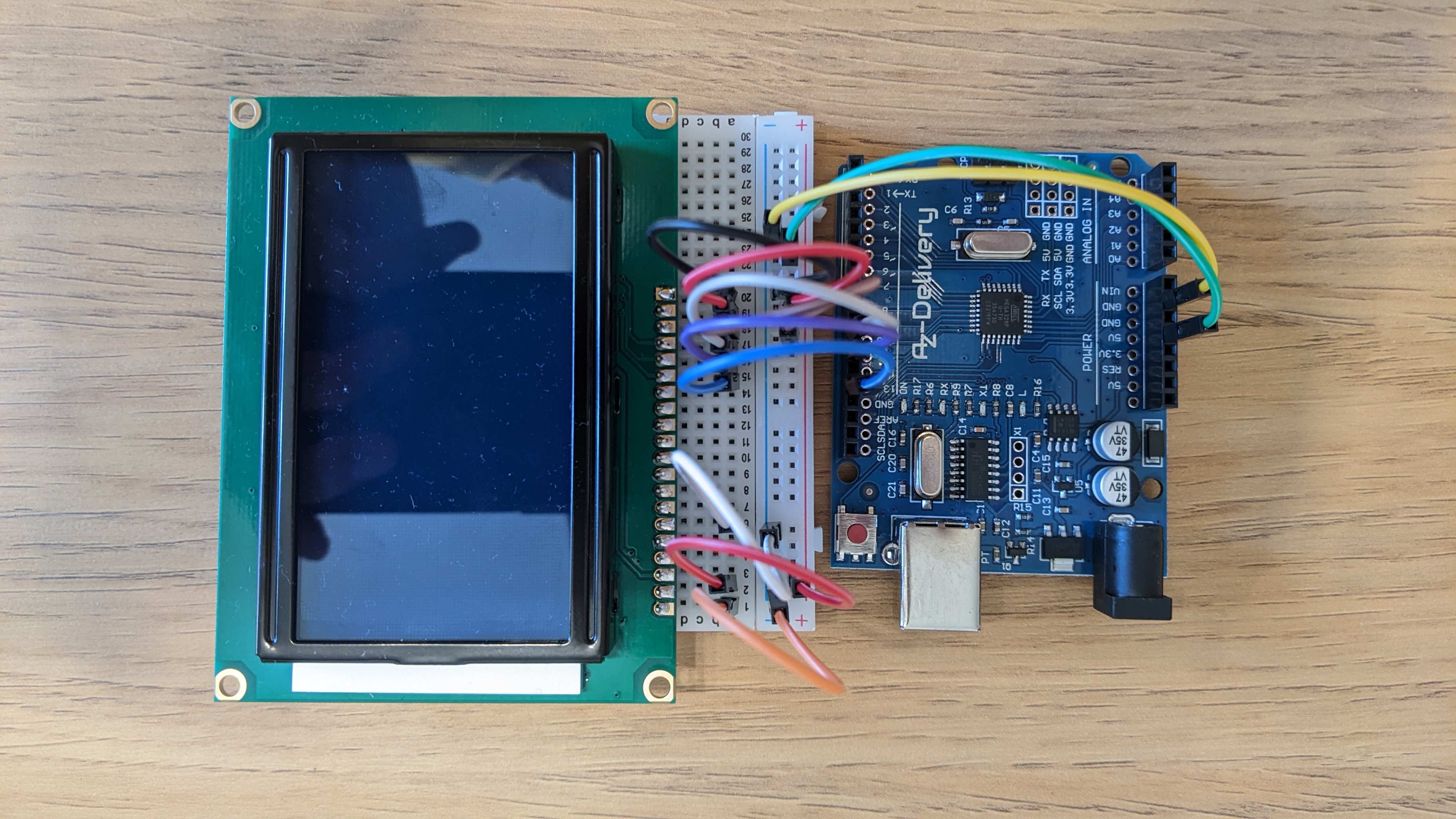
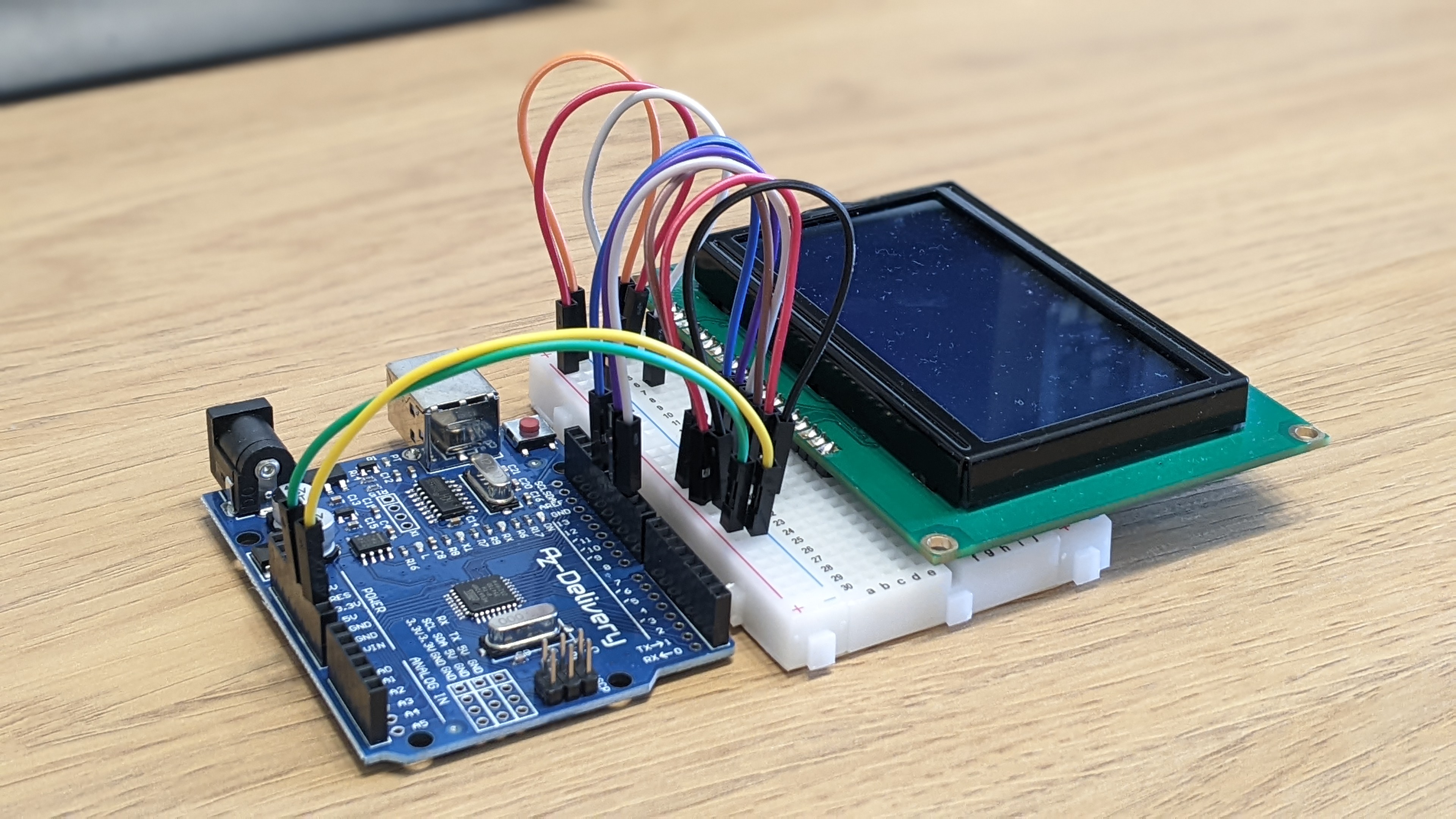
These are some picture of the final result:
Arduino
Now I am going to explain step by step how to configure the Arduino.
-
If you don’t have it installed, the first thing to do is to install the Arduino IDE.
-
Once you have done this you need to install the
u8g2library by clicking on Tools -> Manage Libraries. In the window that opens, search foru8g2and install it. -
You can now open an existing example project by clicking on File -> Examples -> U8g2 -> full_buffer -> HelloWorld.
-
You will have to define a
u8g2object. In my case, none of the previously defined objects worked, so I created a new one:
U8G2_ST7920_128X64_F_SW_SPI u8g2(U8G2_R0, /* clock=*/ 13, /* data=*/ 11, /* CS=*/ 10, /* reset=*/ U8X8_PIN_NONE);
-
Finally, you can tweak the project a bit and upload it to the board.
-
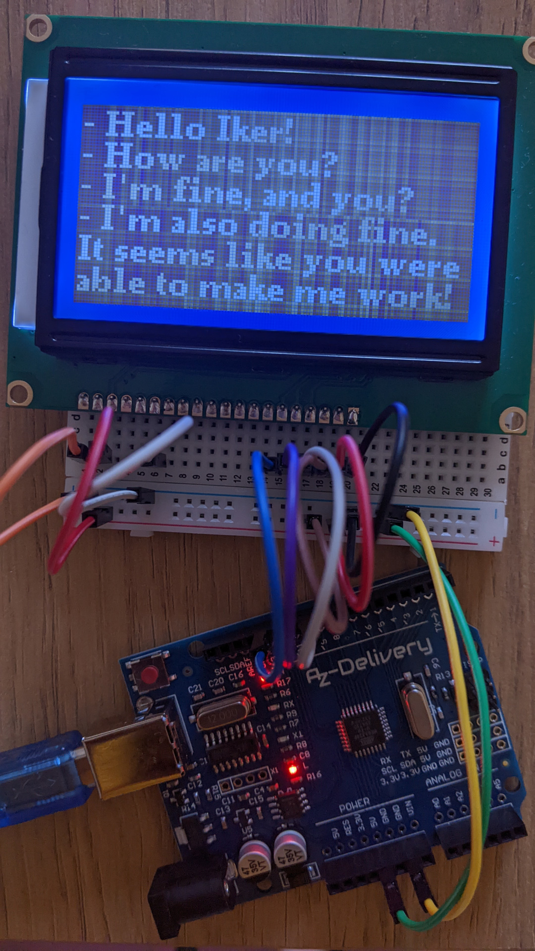
Ta-da! The screen displays the text.
Raspberry
-
The display manufacturer provides a Python driver to control the display on their website2.
-
You also need to edit
/boot/efi/config.txtto expose the SPI interface to user-space.
dtparam=spi=on
- Next, you need to install the Python dependencies.
pip install pypng spidev
- Finally, you need to run the driver.
from st7920 import ST7920

s = ST7920()

s.clear()
s.put_text("Hello world!", 5, 10)
s.redraw()
Note: the last step failed and I had to comment the line that controls the Chip Select line: self.spi.cshigh = True # use inverted CS.
Arduino vs Raspberry
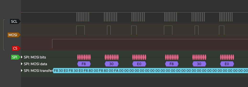
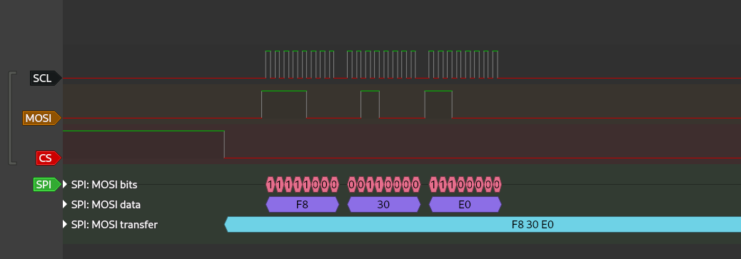
So we come to the important question, why does it work correctly on the Arduino but not on the Raspberry? To answer this question I have used a logic signal to see what each device is sending. If you look at the two images below you will be able to understand it.
 |
|---|
| Arduino |
 |
|---|
| Raspberry |
Exactly, the display accepts an inverted Chip Select line and this is what the Arduino does. Unfortunately, the Raspberry Pi driver does the contrary and I’m unable to change it. So the display is not being selected when sending the information and thus, it can’t be controlled.
Apparently, in recent kernel versions it seems that CS_HIGH is a bus property rather than a device property3, so it is not possible to change it from user-space.
Apart from this, it is also worth noting the time between Raspberry sends, but this should only affect the speed at which the information is displayed on the screen.