Introduction
As mentioned in the previous post, the Chip Select (CS) signal coming from the Raspberry Pi is active-low, while the display needs an active-high signal. It took me a long time (about three months) to understand the intricacies of this configuration for the Linux Kernel and the Raspberry Pi. I won’t delve into the long journey it took me to arrive at the knowledge I needed to change the signal, but I will explain what needs to be done to set the CS signal to active-high.
 | Generated by Gemini AI |
Changing the devicetree (DT) overlay
The necessary configuration to operate this change occurs in the DT1, and this is what I am going to explain in this section.
Explanation
To invert the CS signal we need to set the cs-gpio to ACTIVE_HIGH in the controller AND set the spi-cs-high in the peripheral property. The kernel documentation defines a table where this is explained2. Let me quote it:
There is a special rule set for combining the second flag of an cs-gpio with the optional spi-cs-high flag for SPI slaves.

Each table entry defines how the CS pin is to be physically driven (not considering potential gpio inversions by pinmux):

device node     | cs-gpio       | CS pin state active | Note
================+===============+=====================+=====
spi-cs-high     | -             | H                   |
-               | -             | L                   |
spi-cs-high     | ACTIVE_HIGH   | H                   |
-               | ACTIVE_HIGH   | L                   | 1
spi-cs-high     | ACTIVE_LOW    | H                   | 2
-               | ACTIVE_LOW    | L                   |
We are interested in the third line of the table since it is the one that sets the CS pin to ACTIVE_HIGH. Therefore, and as mentioned above, we need to set both the cs-gpio to ACTIVE_HIGH and set the spi-cs-high property.
Hands-on
In the Fedora distribution, overlays are located in the /boot/efi/overlays folder. The files in this folder are in the Device Tree Blob (DTB) overlay format, which is a binary representation of the DT. The human-readable format is called Device Tree Source (DTS), so you need to disassemble the DTB to obtain a DTS. As an example, you can convert spi0-1cs with the following command:
dtc -I dtb -O dts spi0-1cs.dtbo -o spi0-1cs.dtbs
However, I wouldn’t recommend you to do this dissasembling, but to download the file from the Raspberry Pi repositories3. The dissasembling is a best effort and some data (such as labels) may be lost during this process.
Now let’s focus on the changes. First, you need to set the cs-gpios to ACTIVE_HIGH (or 0) in the SPI4 controller. For that purpose, the target should be a controller, in this case &spi0, and you need to do this in the fragment@1 __overlay__. Example:
fragment@1 {
    target = <&spi0>;
    frag1: __overlay__ {
        cs-gpios = <&gpio 8 0>;
        status = "okay";
    };
};
Second, add a new fragment whose target is the the virtual &spidev0 peripheral with the spi-cs-high property. These devices are exposed to user-space through a /dev/spidevX device node to allow user-space drivers to access the SPI peripherals directly. This is useful when there are no Linux kernel drivers for the devices.
fragment@4 {
    target = <&spidev0>;
    __overlay__ {
        write-only;
        spi-cs-high;
    };
};
This last part is the part that took me so long to understand. The spi-cs-high must be set on the SPI peripheral property and not on the SPI controller.
Once this is done, you can compile it to dtbo format:
dtc -@ -I dts -O dtb spi0-1cs.dtbs -o spi0-1cs.dtbo
The file should be present in its original location in the /boot/efi/overlays folder.
You can check the results live after a reboot with:
dtc -I fs /sys/firmware/devicetree/base
The two properties should be changed, one at the controller level and the other at peripheral level.
spi@7e204000 {
    ...
    cs-gpios = <0x07 0x08 0x00>;
    spidev@0 {
        #address-cells = <0x01>;
        spi-cs-high;
        ...
    };
...
}
The complete DT is available here.
Signal results
This is the output signal from the Raspberry Pi:

As you can see, the CS line is set to active-high, which means we are on the right track to print something on screen.
Additional changes (necessary for the driver to work properly)
In the previous post I mentioned a Python driver to control the display. I had to make a couple of additional modifications to make it work. The first is to comment out the change to the CS_HIGH property. If this change is not made the driver crashes because this property is not available and can no longer be changed from the driver itself. Apart from that you also have to change the bus transfer rate to 600k. Without further ado, here are the changes:
#self.spi.cshigh = True
self.spi.max_speed_hz = 600000
End result
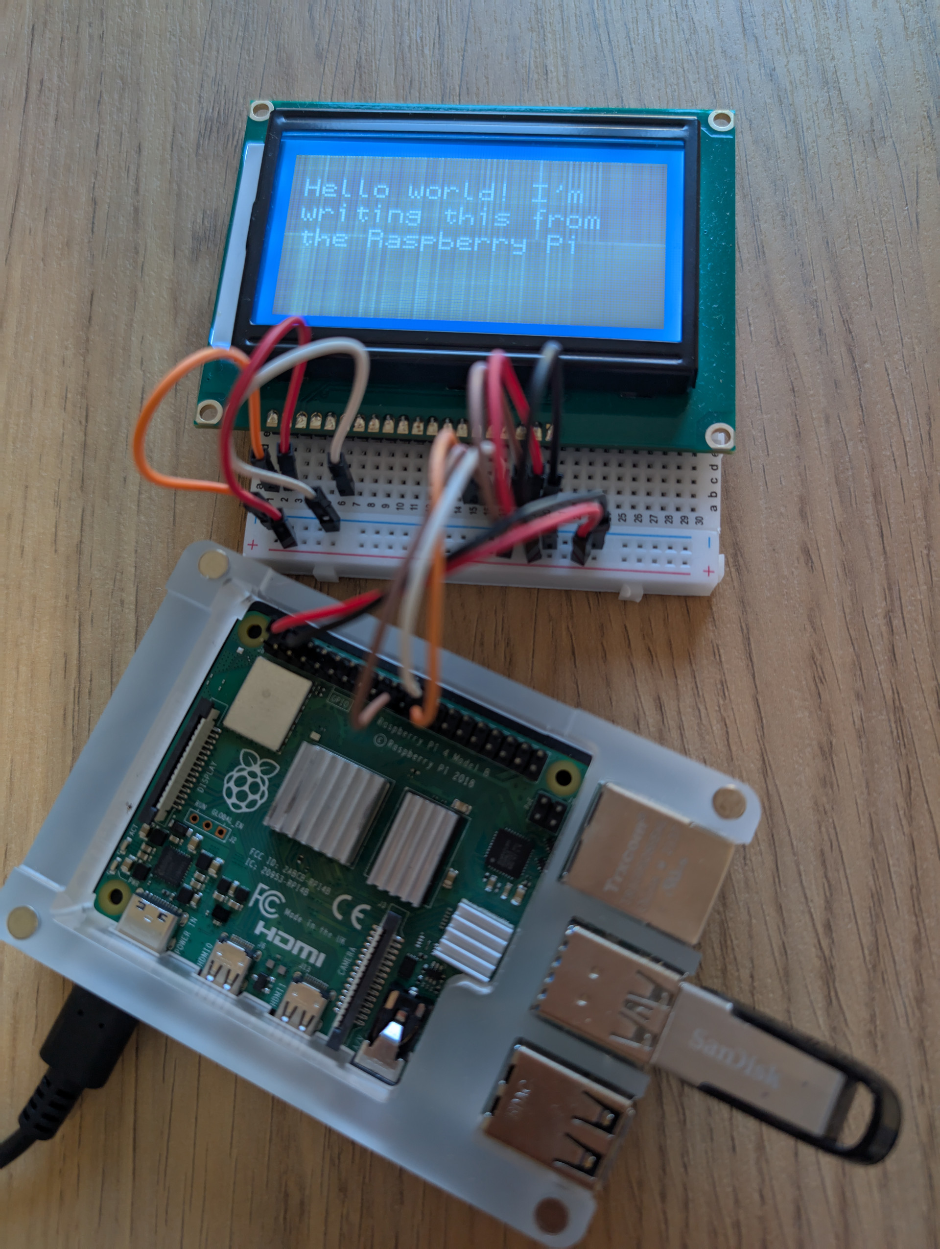
Finally, you need to run the drive from the Python console:
from st7920 import ST7920

s = ST7920()

s.clear()
s.put_text("Hello world! I'm", 5, 10)
s.put_text("writing this from", 5, 20)
s.put_text("the Raspberry Pi", 5, 30)
s.redraw()
Voilá:

Conclusion
Understanding the problem took time, but the learning journey was incredibly rewarding. I gained valuable insights and skills, and I couldn’t have done it without the help of the Raspberry Pi forum community5. Thanks to everyone who offered their support and guidance. Your assistance was invaluable and greatly appreciated.